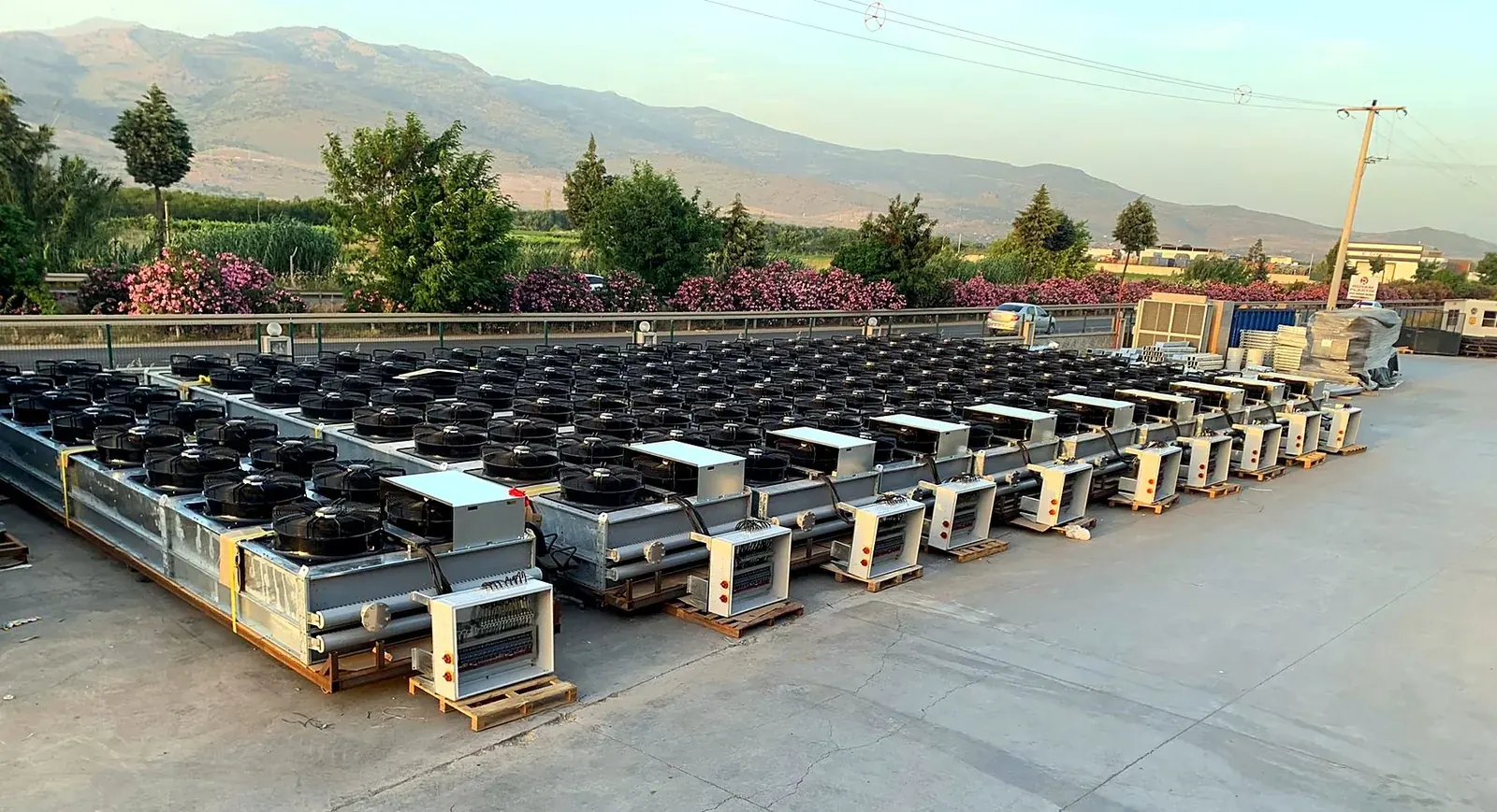
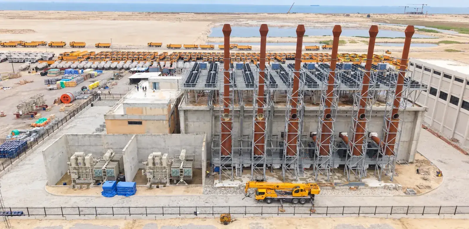
A finned tube heat exchanger - a finned coil - is the working part of every radiator, dry cooler and air-cooled condenser. Liquid flows inside tubes; air flows across them; and because air transfers heat so much worse than water, the outside of the tubes is multiplied by thin fins until the two sides are in balance. A good coil puts fifteen to twenty square metres of fin surface on every square metre of face, and the designer's craft is in choosing the tube, the fin, the pitch and the rows for the duty and the site.
This guide explains the parts of a finned coil and what each choice does.
Tubes, Fins And How They Are Joined
The standard coil for engine radiators and dry coolers is copper tube with aluminium fins. Copper conducts heat well, is easy to braze and resists water-side corrosion; aluminium is light, cheap and a good conductor for the fin. The fins are stamped with collars, stacked on the tubes, and the tubes are mechanically expanded so that the collars grip them tightly - the quality of that contact is the quality of the coil. Steel tubes are used for high pressures and for some process duties; stainless steel for aggressive fluids.
The fin itself can be flat or corrugated. Corrugated and louvred fins disturb the air and raise the heat transfer per square metre at the cost of pressure drop and of a tendency to hold dirt; flat fins are the choice for dusty sites and for coils that must be cleaned often.
Fin Pitch, Rows And Circuits
Fin pitch is the distance between fins, typically 2 to 4 mm. A close pitch packs the most surface into the coil and gives the shortest, cheapest unit for clean air; a wide pitch gives less surface per metre but clogs far more slowly, so it is chosen where the air carries sand, cement dust, seeds or fibres. Rows are the depth of the coil in the direction of the air: more rows mean more surface and a greater air-side pressure drop, so the fans work harder; two to six rows cover most duties.
Circuits are the number of parallel paths the liquid takes through the tubes. They set the velocity in the tubes - fast enough for good heat transfer and to avoid laminar flow and fouling, slow enough to avoid erosion of the copper - and with the number of passes they set the liquid-side pressure drop. For an engine radiator the engine maker's limit on external pressure drop decides the circuiting before anything else: a coil that exceeds it starves the engine of flow.
Materials For Coast, Desert And Industry
Plain aluminium fins last in a C3 atmosphere. Salt attacks them and the galvanic couple between copper tube and aluminium fin eats the fin from the collar outwards until it no longer conducts heat. For coastal, offshore and industrial sites - C4, C5-M, CX to ISO 12944 - the fins are made of AlMg2.5, a seawater-resistant alloy, or the whole coil is epoxy-coated after manufacture, or both. The coating adds a small thermal resistance that the design accounts for; it is tested in neutral salt spray to ISO 9227.
The casing follows the same class: hot-dip galvanised steel for C3 and C4, galvanised and painted with a duplex system or stainless steel for C5. Fasteners, guards and glands match the casing, and the corrosion class and the protection system are printed on the datasheet.
Hot Air, Thin Air And The Coil
A coil designed for 35 °C ambient is too small at 50 °C, because the temperature difference that drives the heat across the fins has shrunk by a third. At altitude the air is thinner - 10 % less dense per 1,000 m - so the same fans move less mass and the coil needs more airflow or more surface. Humid air carries vapour that must be heated too. None of this changes the coil's construction; it changes its size, and the datasheet states the ambient, the altitude and the humidity basis the capacity belongs to.
TECS builds its finned coils in its own factory in İzmir - tubes, fins, expansion, brazing and pressure test - and designs each coil for the duty and the site. For a coil or a complete radiator, send the heat duty, the flows, the temperatures and the site conditions, or send the engine data sheet.
In Short
Fins multiply the air-side surface fifteen to twenty times
Copper tube and aluminium fin as standard; AlMg2.5 and epoxy coating for aggressive sites
Fin pitch 2 to 4 mm: close for clean air, wide for dust
Rows set surface and air-side pressure drop; circuits set tube velocity and liquid-side pressure drop
The engine maker's pressure drop limit decides the circuiting of a radiator coil
TECS makes its coils in its own factory and designs each for the duty and the site
Aluminium conducts heat well enough for a thin fin, weighs a third of copper and costs far less. Copper fins are used only in special cases; for corrosion the answer is an aluminium-magnesium alloy or a coating, not copper.
What fin pitch is right for my site?
Close pitches for clean air and the most compact unit; wider pitches where the air carries dust, seeds or fibres, because the coil must keep its airflow between cleanings. The choice is made in the design for the site, together with the fin shape.
Does more rows always mean more capacity?
More surface, yes, but the air warms up as it passes each row, so each additional row adds less than the last, and the air-side pressure drop rises with every row. Beyond a certain depth a longer or wider coil is the better way to add capacity.
Can a coil be replaced in an existing radiator?
Usually yes: the coil is built to the casing's dimensions and connections. It is also the moment to change the fin material or the pitch if the original did not suit the site.
How is a coil tested?
Every TECS coil is pressure-tested in the factory before it leaves; the test pressure and the result are in the test record delivered with the unit.
Send us the heat duty, the fluid temperatures and flow rates, the ambient conditions and the installation limits. We answer with a design proposal - or write to us on WhatsApp.