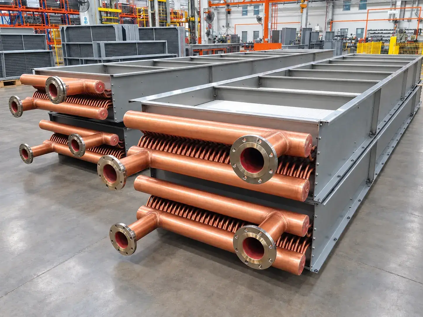
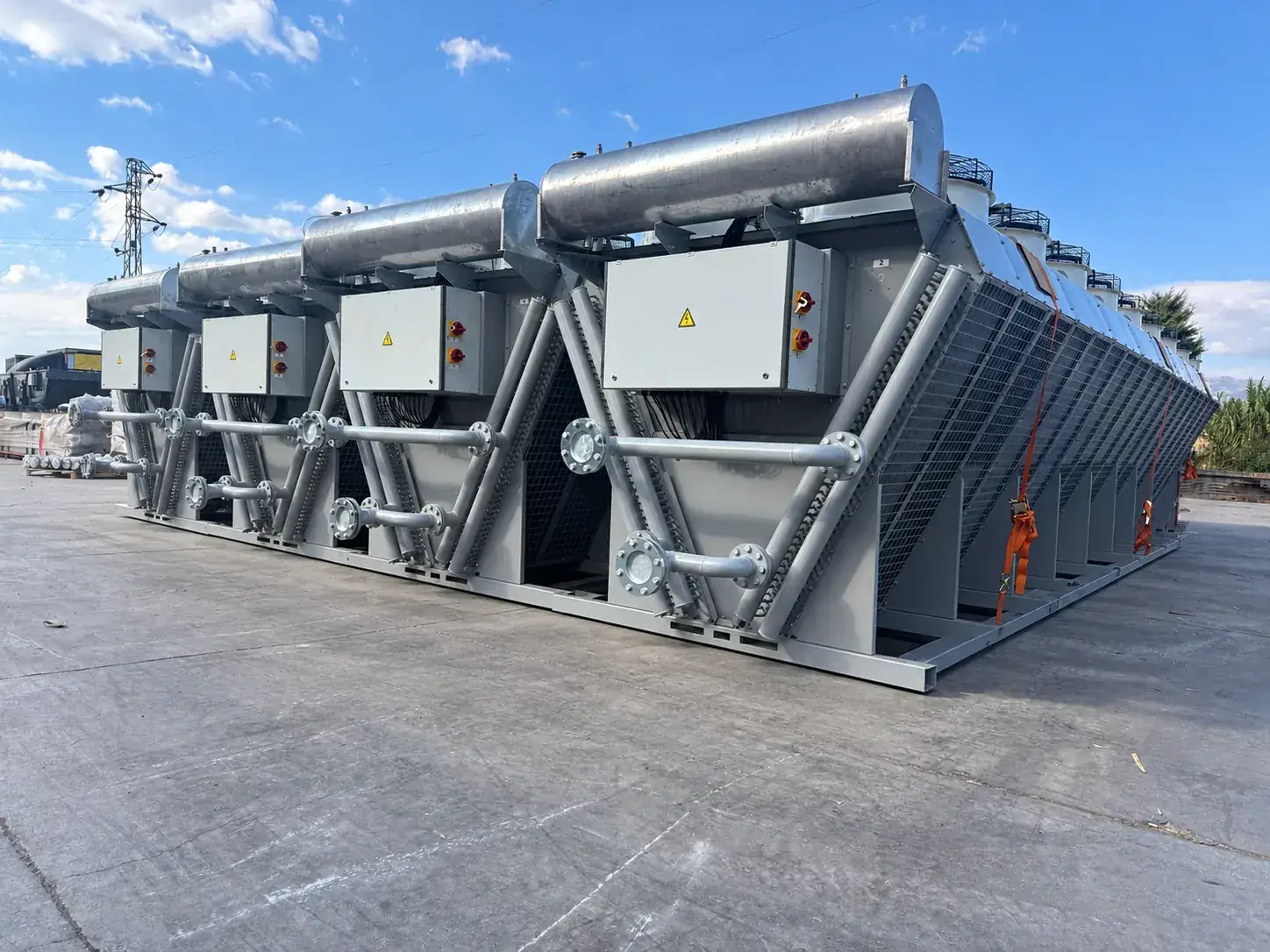
Radiators for liquid-cooled IT loads and free-cooling circuits. Approach temperature, fan control and redundancy are set at project level with the cooling architecture of the site.
Liquid-cooled server racks and free-cooling chillers need radiators that reject the IT load at the hottest hour of the year and run at a fraction of the fan power for the rest of it. TECS designs V-type and horizontal radiators for the approach temperature of the cooling architecture, with EC fans, redundancy of fans and units, and sound levels suited to urban sites.
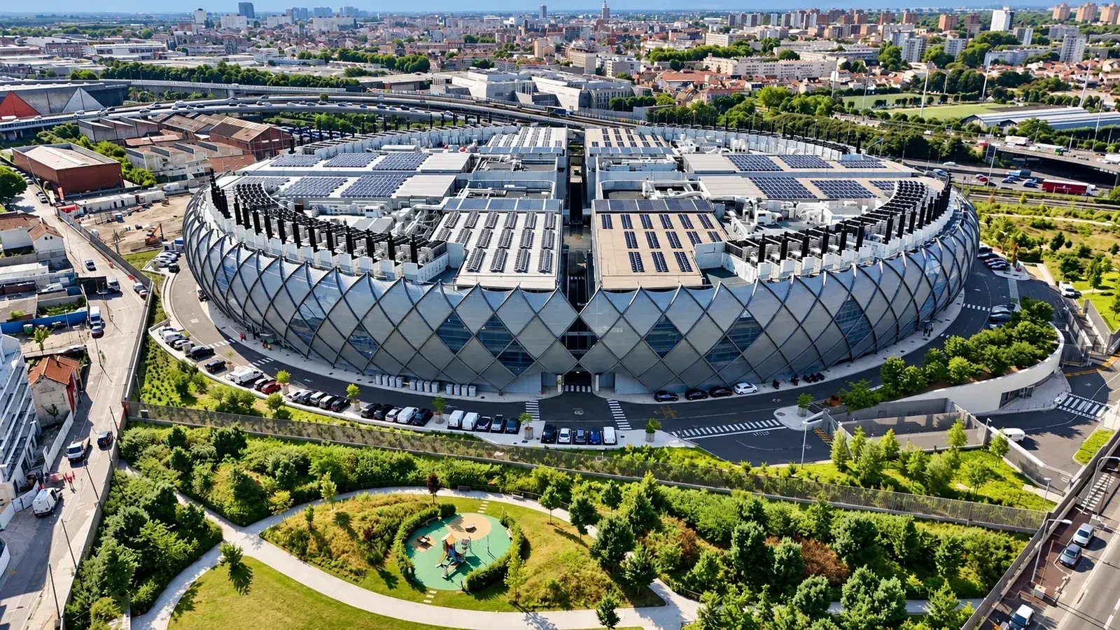
One of the largest data centers in Europe is cooled with TECS radiators on its roof.
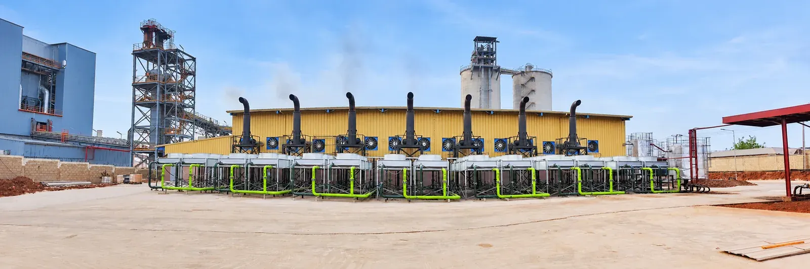
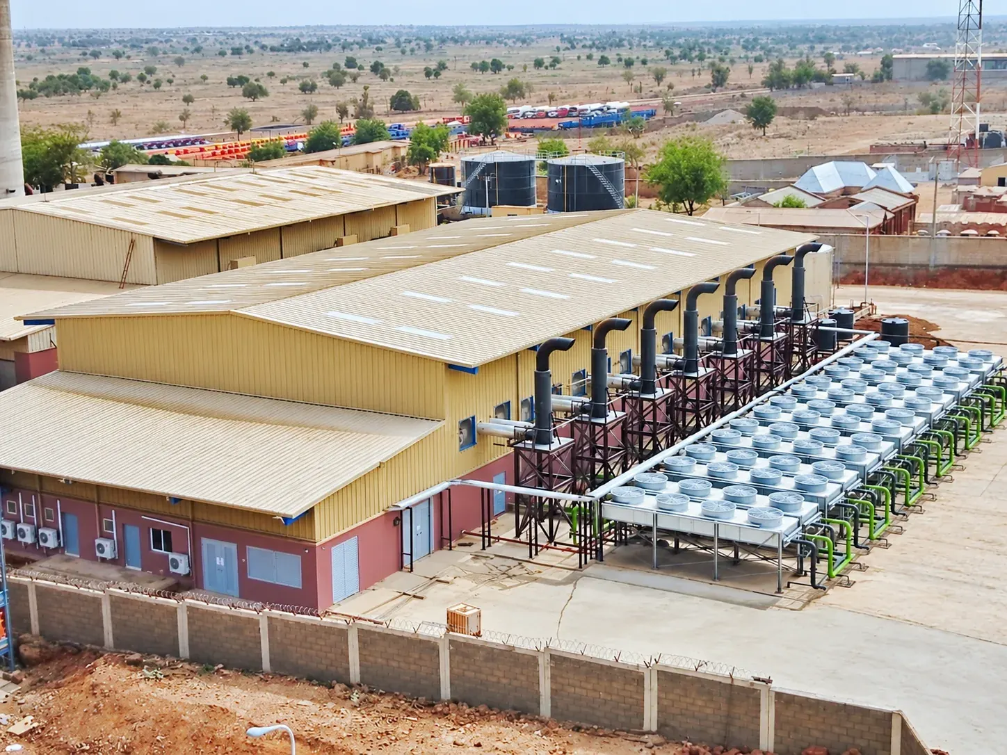
Engine-mounted radiators and electrically driven remote coolers for diesel and gas generator sets. Separate LT and HT circuits are arranged around the engine interfaces, with the heat rejection, flow rate and allowable pressure drop taken from the engine manufacturer.
For a generator set the radiator is part of the engine: it must reject the jacket-water, charge-air and oil heat at the hottest ambient of the site while the coolant pressure drop and the fan power stay inside the engine manufacturer's figures. TECS supplies three answers to that duty - the engine-driven mechanical radiator, the vertical remote radiator with electric fans and the horizontal radiator for remote installation - and designs each for the engine data of the project.
Single-circuit and LT/HT arrangements, 50 and 60 Hz fans, dusty, coastal and desert specifications and sound limits down to the levels of residential sites are everyday work. For containerised generator sets the radiator is matched to the container air inlet and outlet together with AXON Technic.
Combined heat and power plants cannot always use all of the recovered heat. A radiator rejects the remaining load to ambient air so the engine keeps running at full output whatever the heat demand.
Gas-engine CHP plants recover heat from the jacket water, the exhaust and the intercooler to make hot water for district heating, greenhouses or industry. When the heat demand is lower than the engine's output, an emergency cooler takes over so the engine can keep generating. TECS sizes that radiator for the full LT and HT heat of the engine at the design ambient, with EC fans that run only as fast as the load needs.
Heating modules with pumps, control valves and heat exchangers complete the circuit, and expansion tanks, level switches and control panels are supplied with the cooler for one coordinated system.
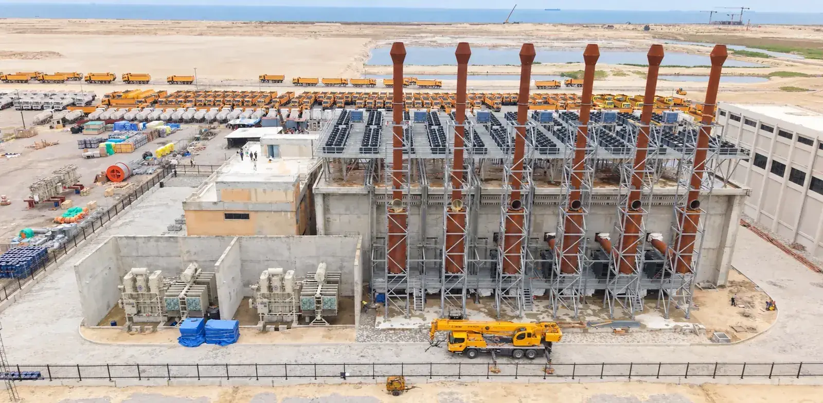
Multi-engine stations in the tens of MW need cooling banks coordinated with the plant layout: air recirculation, pipe routes, noise and maintenance access are reviewed for the whole bank, not one unit.
Engine power plants of tens of megawatts run ten to fifty generator sets side by side, each with its own radiator on an elevated steel structure or a platform. Here the bank is designed, not the unit: the air drawn by one row must not be the warm air discharged by the next, pipe routes and expansion tanks must suit the plant layout, and the sound of the whole bank at the fence must meet the permit.
TECS delivers these banks as identical, factory-tested units - 24, 48 or 96 of a kind - with CFD studies of the recirculation where the layout is tight and with project documentation for the plant engineering.
Inlet air heating and cooling coils keep the turbine output close to its ISO rating when the ambient moves away from 15 °C. Coil geometry, pressure drop and inlet house interfaces are designed together.
Gas turbine output follows the inlet air density. Heating coils in the inlet house keep the air above the icing point and improve part-load efficiency in winter; cooling coils raise the output on hot days. The coil is designed for the inlet house dimensions, the airflow and the smallest possible air-side pressure drop, in copper or stainless steel with aluminium, AlMg2.5 or coated fins.
TECS has supplied inlet heating and cooling coils for gas turbines from a few megawatts in cogeneration to large units in combined-cycle plants.
Free-cooling radiators that take the load off the chiller whenever the ambient allows. Control sequences, freeze protection and the chiller interface are assessed with the seasonal climate of the site.
When the outdoor air is cold enough, a radiator in the chilled-water or condenser-water circuit takes the load off the chiller and the compressor stops: free cooling. The number of free-cooling hours depends on the climate, the water temperatures and the control sequence, so the radiator is sized with the seasonal weather data of the site.
Glycol percentage, freeze protection, the chiller interface and the control logic are agreed with the system designer before the unit is sized.
Send us the heat duty, the fluid temperatures and flow rates, the ambient conditions and the installation limits. We answer with a design proposal - or write to us on WhatsApp.