Products

01 / Compact heat exchange layout

V-Type Radiators

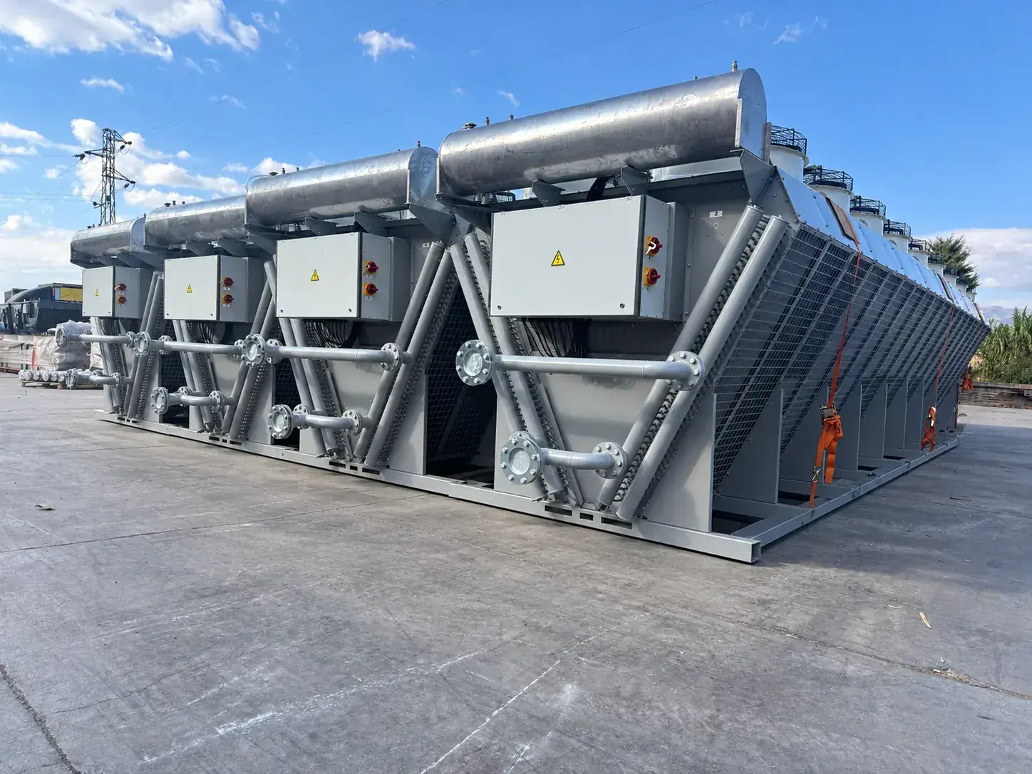
V-type radiators combine two inclined coils under a common row of top-mounted fans. The arrangement carries large capacities on a short footprint and suits power plants, data centers and chiller economiser circuits where many units stand side by side.

  • Single-circuit or LT/HT V-type units with the coil angle, fan diameter and fan count chosen for the duty and the sound limit.
  • Common frame with lifting points, pipework and junction boxes prepared for fast site installation.
  • EC fans with speed control for part-load operation and low night-time sound levels.
  • Materials and coatings for coastal, desert and industrial atmospheres.

ApplicationsPower PlantsData CentersChiller Economisers

Request a design

Why A V

Two coils inclined under a common row of fans give almost twice the heat exchange surface of a flat unit on the same ground area. V-type units are therefore chosen where many units stand side by side and ground is expensive: power plants, data centers and chiller economiser circuits.

Thermal Design

The coil angle, the fin pitch and the number of fans are solved together for the duty and the site ambient. Every unit is sized so that the two coils share the airflow evenly and the fans draw through both at the required face velocity; the design checks the air recirculation between neighbouring units in a bank.

Fans And Control

EC fans with integrated speed control are the usual choice: at part load and at night they run slower, which saves power and lowers the sound level. AC fans with external speed control are available where the site specification asks for them.

Frame And Connections

A common galvanised or painted steel frame carries both coils, the fan deck, the headers and the junction boxes, with lifting points for the crane. Flanged connections, expansion tank, level switch and control panel are fitted at the factory, so the unit is connected and started on site in a short time.

Typical Scope Of Supply

  • Two inclined coils with headers and flanged connections
  • Common steel frame with fan deck and lifting points
  • EC fans with speed control (or AC fans)
  • Junction boxes or control panel
  • Expansion tank with level switch
  • Factory pressure test and function test
  • Datasheet, dimensional drawing, fan curve, acoustic data, IOM manual

Technical Overview

Arrangement
V-type, top-mounted induced-draught fans
Circuits
Single circuit or LT/HT
Fans
EC / AC axial fans
Capacity
Multi-unit arrangements for MW-class plants
Materials
Cu/Al, AlMg2.5, epoxy coating, galvanised or painted casing
Options
Speed control, expansion tank, control panel, protection guards

02 / Remote heat rejection

Horizontal Remote Radiators

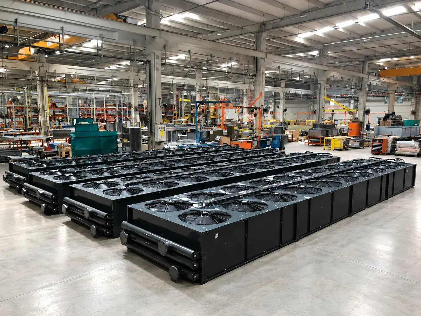
Horizontal radiators reject the heat of engines, cogeneration circuits and processes to ambient air where the equipment must be positioned away from the heat source. Each unit is sized for its duty: heat exchange surface, fan quantity, airflow and sound level are selected together for the required capacity and the design ambient.

  • Single-circuit units and combined LT/HT units for gas and diesel generator sets, with separate low- and high-temperature circuits built into one casing.
  • Finned-tube coils in copper tube / aluminium fin as standard; AlMg2.5 fins, epoxy-coated fins and coated casings for dusty, coastal, offshore and other demanding environments.
  • EC or AC axial fans with the required IP rating and motor class; speed control, fan diffusers and silencers where the sound limit asks for them.
  • Delivered with support legs, expansion tank, coolant level switch, junction box or control panel and the pipe connections defined for the project.

ApplicationsPower GenerationCogenerationPower PlantsData CentersChiller Economisers

Request a design

Thermal Design

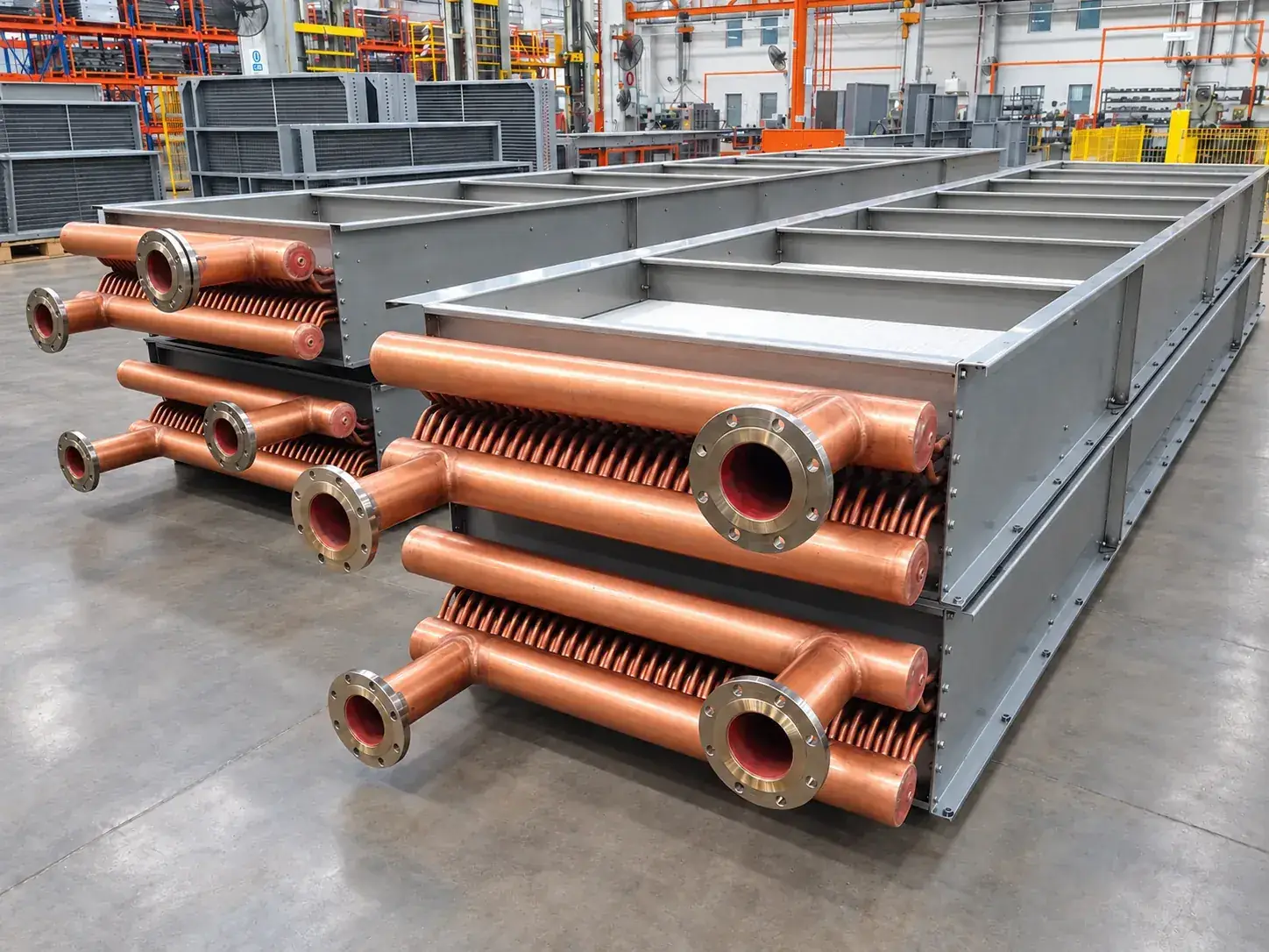
The coil is built from TECS finned-tube geometry: copper tubes expanded into aluminium fins, with the fin pitch chosen for the duty and the site. Dusty sites get a wider pitch so the coil stays clean; clean sites get a denser pitch and a shorter unit. Rows, passes and circuiting are selected so that the coolant pressure drop stays inside the engine manufacturer's limit while the heat transfer stays high.

Air Side

The number of fans, their diameter and the finned length per fan follow the airflow the coil needs at the design ambient. Induced-draught units carry the fans above the coil and draw the air through it; forced-draught (pusher) units blow through the coil with the fans underneath and the motors in cooler air. Fan performance is taken at the site air density, so a unit for a high-altitude site is sized for the thinner air it will actually move.

Sound

The sound power of the delivered fans, the number of fans and the distance to the receiver give the sound pressure level at the distances the enquiry asks for. A safety margin is held between the calculated level and the limit. When the limit is tight, lower fan speeds, more fans at lower speed, EC fans with speed control or acoustic diffusers bring the unit inside the limit.

Materials And Corrosion

Copper tube with aluminium fin is standard. For coastal, offshore, desert and chemical atmospheres the fins are AlMg2.5 or epoxy coated and the casing is hot-dip galvanised or painted to the corrosion category of the site, up to C5-M. Expansion tanks are stainless steel SS304L or SS316L.

Typical Scope Of Supply

  • Finned-tube coil(s) with headers and flanged connections
  • Galvanised or painted steel casing and support legs
  • EC or AC axial fans with guards
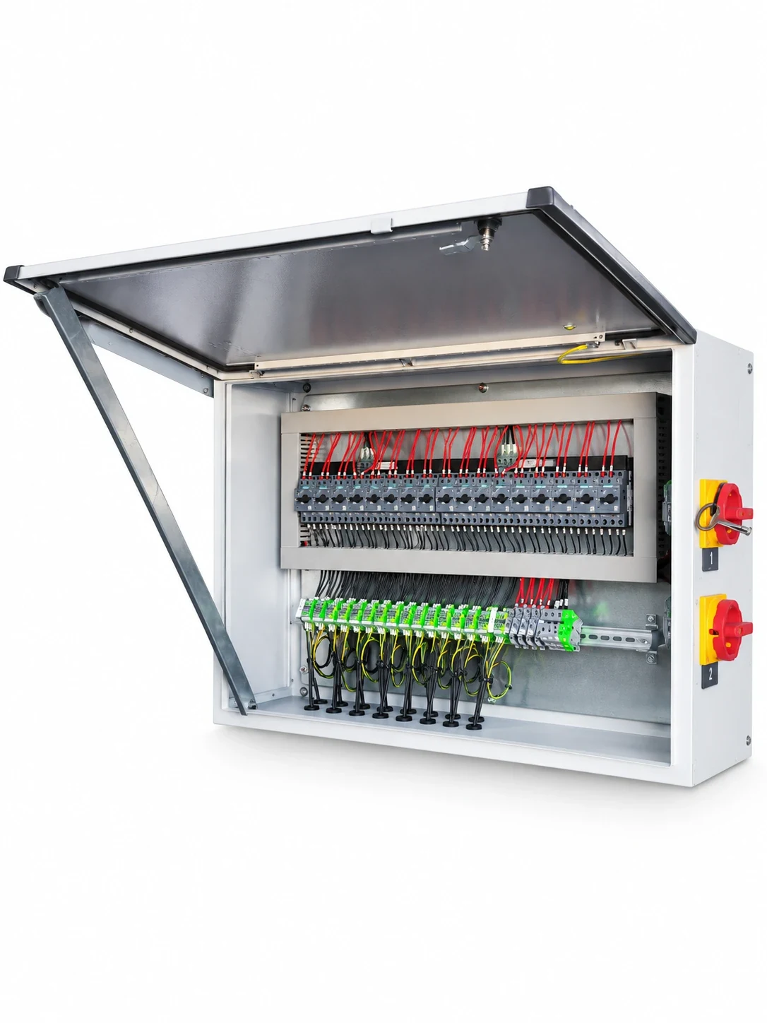
  • Junction box or control panel with isolators
  • Expansion tank (SS304L / SS316L) with level switch
  • Coil protection guard (forced-draught units)
  • Factory pressure test and function test
  • Datasheet, dimensional drawing, fan curve, acoustic data, IOM manual

Technical Overview

Arrangement
Horizontal, induced or forced draught
Circuits
Single circuit or LT/HT
Length
From about 1 m up to 13 m per unit
Fans
EC / AC axial fans, 50 or 60 Hz
Materials
Cu/Al, AlMg2.5, epoxy coating, galvanised or painted casing
Options
Expansion tank, level switch, control panel, diffusers, silencers

03 / Electric fan configurations

Vertical Remote Radiators

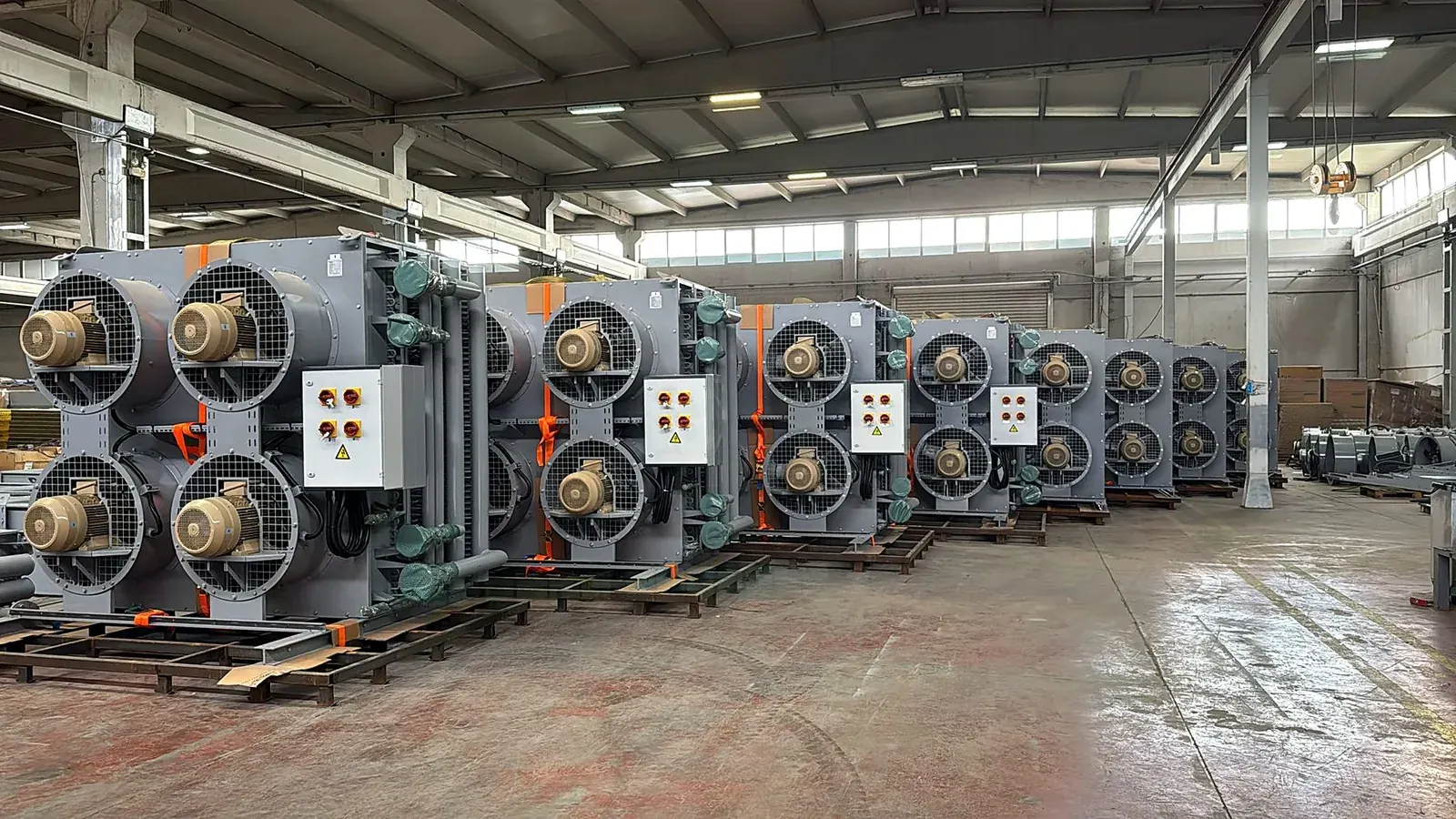
Vertical remote radiators move the cooling duty away from the engine when the engine room, the noise limit or the plant layout does not allow an engine-mounted radiator. The coil stands upright and the electric fans blow or draw the air horizontally, so the unit fits against a wall, a louvre or a duct.

  • Single-circuit or LT/HT coils with the circuit arrangement matched to the engine manufacturer's flow, temperature and pressure-drop requirements.
  • Electric fan sets selected for the airflow, the external pressure drop of ducts and louvres, the ambient temperature and the sound level.
  • Frame, fan guards, pipe connections and junction box built as one factory-tested unit ready for installation.
  • Suitable for container installations, power plants and multi-engine stations with many identical units.

ApplicationsPower GenerationPower Plants

Request a design

Where It Is Used

A vertical remote radiator takes the engine cooling duty out of the engine room. It stands against a louvre, in a duct or in the open, and its electric fans are independent of the engine, so the engine room stays quieter and cooler and the radiator can be placed where the air is.

Thermal Design

Each unit is sized with the TECS design software for the heat rejection, flow rate and inlet/outlet temperatures given by the engine manufacturer. Single-circuit units cool one jacket-water loop; LT/HT units carry the low-temperature (charge air, oil) and high-temperature (jacket water) circuits in one casing with separate headers and connections. The fin pitch, rows and circuiting are chosen so both circuits meet their temperatures at the design ambient without exceeding the allowable pressure drop.

Fans And Electrics

One to eight EC or AC axial fans per unit, selected for the airflow, the external pressure of ducts and louvres, the ambient temperature and the sound limit. Motors are specified to the site supply (50 or 60 Hz, IP class, insulation class), wired to a junction box or a control panel with isolators and, where requested, speed control.

Installation

Units are delivered as one factory-tested assembly: coil, casing, fans, guards, expansion tank and pipe connections. Lifting points, support frames and anti-vibration mounts are defined with the installation; flanged or grooved connections are placed to suit the pipe routes of the site.

Typical Scope Of Supply

  • Single-circuit or LT/HT coil with headers and connections
  • Casing, support frame and lifting points
  • EC or AC axial fans with guards
  • Junction box or control panel
  • Expansion tank with level switch
  • Factory pressure test and function test
  • Datasheet, dimensional drawing, fan curve, acoustic data, IOM manual

Technical Overview

Arrangement
Vertical coil, horizontal airflow
Circuits
Single circuit or LT/HT
Fans
EC / AC axial fans, 1 to 8 fans per unit
Installation
Free standing, against louvres or ducted
Materials
Cu/Al, AlMg2.5, epoxy coating, galvanised or painted casing
Options
Expansion tank, level switch, control panel, protection guards

04 / Engine-driven cooling

Mechanical Driven Radiators

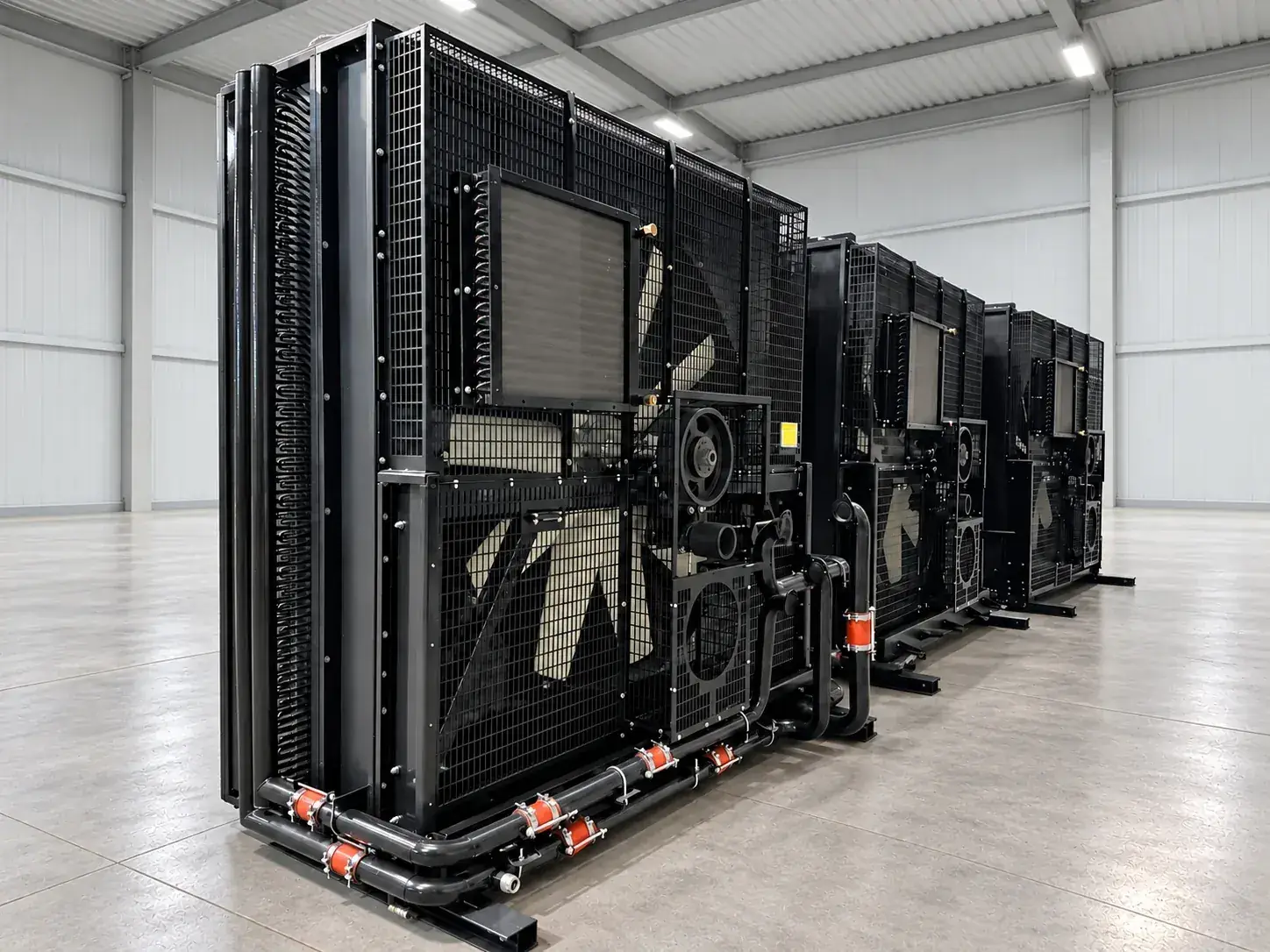
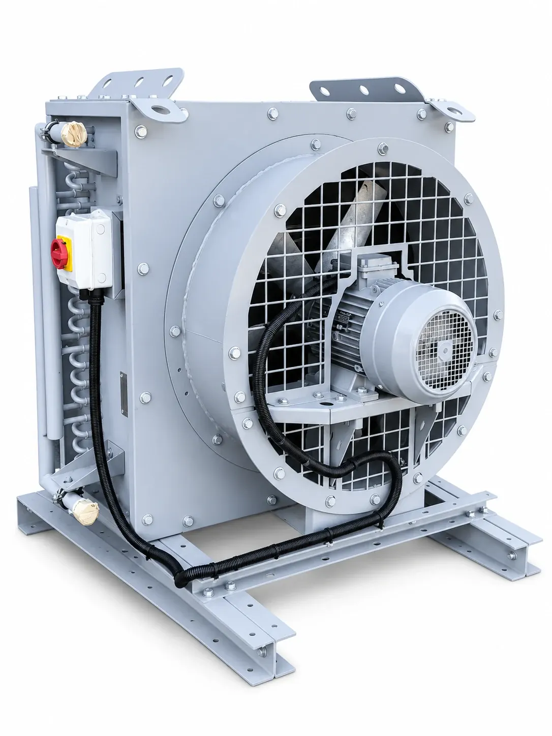
Mechanical driven radiators take their fan power from the engine crankshaft through a belt drive or a shaft. They are the compact, self-contained cooling solution for generator sets where no electric fan power is wanted and the radiator sits in front of the engine.

  • Single-circuit and LT/HT radiator packages with fan, fan drive, guards, frame and pipework built around the engine interfaces.
  • Fan diameter, blade angle and speed matched to the engine fan-drive power and the airflow restriction of the installation.
  • Charge-air cooler, oil cooler and fuel cooler sections integrated into the same core where the engine needs them.
  • Designed for the engine manufacturer's coolant flow, heat rejection and allowable pressure drop at the site ambient.

ApplicationsPower Generation

Request a design

Where It Is Used

A mechanical driven radiator is the self-contained cooling solution for a generator set: the fan is driven by the engine through a belt or a shaft, no electric fan power is needed and the radiator stands in front of the engine on the same base frame or on its own frame.

Thermal Design

The package is designed for the engine manufacturer's heat rejection, coolant flow and allowable pressure drop. Single-circuit and LT/HT cores are built from the TECS finned-tube geometry; where the engine needs them, charge-air, oil and fuel cooler sections are integrated in the same core and air stream.

Fan Drive

The fan diameter, blade angle and speed are matched to the fan drive power the engine provides and to the airflow restriction of the installation: louvres, ducts, exhaust silencers and the engine itself all sit in the air path. Belt drive with tensioner or direct shaft drive, fan guards and flexible connections are part of the package.

Delivery

The radiator is delivered as one assembly with its frame, fan, drive, guards, expansion tank, level switch and connections, pressure tested and ready for the generator set. Packages for container installations are matched to the container air inlet and outlet.

Typical Scope Of Supply

  • Radiator core, single-circuit or LT/HT, with CAC / oil / fuel sections as required
  • Frame, fan, belt or shaft drive, guards
  • Expansion tank with level switch
  • Flexible connections
  • Factory pressure test
  • Datasheet, dimensional drawing, IOM manual

Technical Overview

Arrangement
Vertical core, engine-driven fan
Circuits
Single circuit, LT/HT, with CAC / oil sections
Drive
Belt drive or shaft drive from the engine
Fans
Axial fans, pusher or puller
Materials
Cu/Al, AlMg2.5, epoxy coating, painted frame
Options
Expansion tank, level switch, fan guards, flexible connections

05 / Inlet air conditioning

Gas Turbine Inlet Coils

The output and efficiency of a gas turbine follow the density of the inlet air. Heating coils protect the inlet against icing and improve part-load behaviour in winter; cooling coils recover output on hot days. TECS designs both for the inlet house geometry, the airflow and the air-side pressure drop the turbine allows.

  • Heating and cooling coils in copper or stainless-steel tube with aluminium, AlMg2.5 or coated fins.
  • Coil geometry, row count and face velocity selected for the duty with the lowest air-side pressure drop.
  • Frames, headers and connections built to the inlet house dimensions and the fluid circuit of the plant.
  • Drain pans, droplet eliminators and access for cleaning and inspection defined with the inlet system.

ApplicationsGas Turbines

Request a design

Why Inlet Conditioning

A gas turbine breathes a fixed volume of air; its power follows the density of that air. On a hot day the output falls noticeably below the ISO rating, and in cold, humid weather the inlet can ice. Heating coils protect the inlet and improve part-load behaviour in winter; cooling coils recover output in summer.

Coil Design

The coil is designed for the inlet house geometry, the airflow and the air-side pressure drop the turbine can accept: every pascal lost at the inlet costs output. Face velocity, rows and fin pitch are selected for the duty with the lowest pressure drop; the fluid circuit (hot water, glycol or a heat-recovery loop) is matched to the plant.

Materials

Copper or stainless-steel tubes with aluminium, AlMg2.5 or epoxy-coated fins; galvanised or stainless-steel casing; drain pans and droplet eliminators where cooling below the dew point is expected. Access for cleaning and inspection is defined with the inlet system.

Typical Scope Of Supply

  • Heating and/or cooling coil with headers and flanged connections
  • Galvanised or stainless-steel casing to the inlet house
  • Drain pans and droplet eliminators where required
  • Factory pressure test
  • Datasheet and dimensional drawing

Technical Overview

Function
Inlet air heating, cooling or both
Tubes
Copper or stainless steel
Fins
Aluminium, AlMg2.5, epoxy coated
Fluids
Water, glycol mixtures, heat recovery circuits
Casing
Galvanised or stainless steel
Options
Drain pans, droplet eliminators, flanged connections

06 / Integrated solutions

Heating Module / Skid Frame

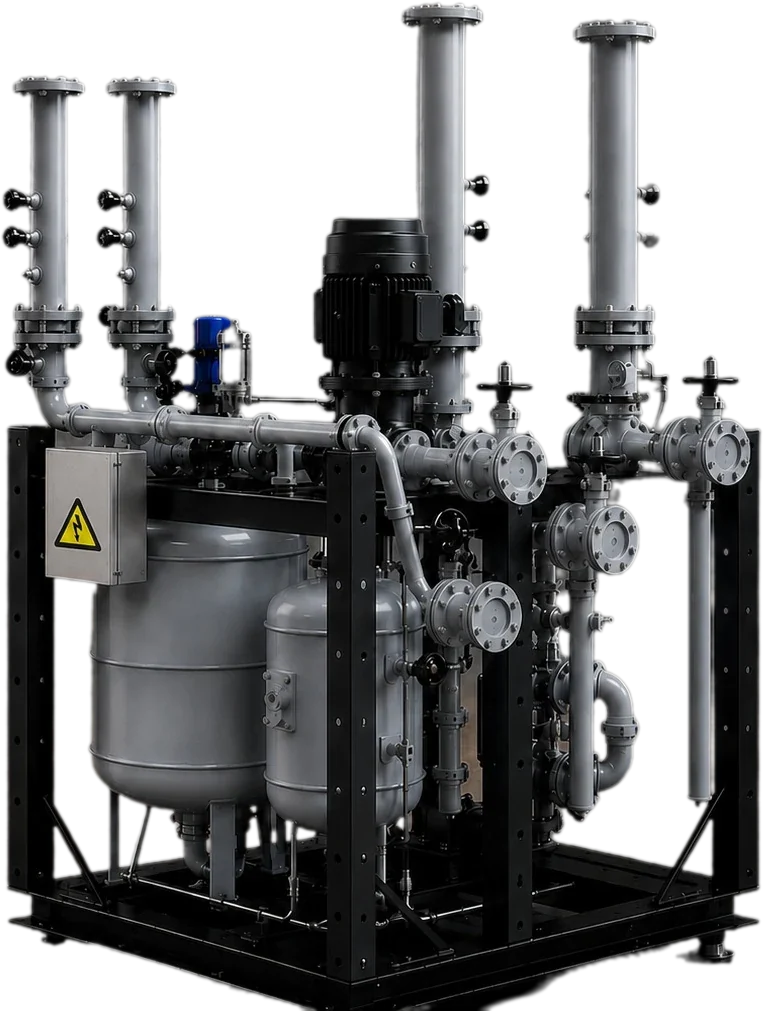
Where the project asks for more than the heat exchanger, TECS supplies the heating module or pump skid that completes the circuit: pumps, three-way valves, expansion tank, instrumentation and pipework on one frame, factory assembled and pressure tested.

  • LT/HT heating modules for gas-engine stations with pumps, control valves and heat exchangers mounted on a common skid.
  • Skid frames and support structures for radiators and auxiliary equipment.
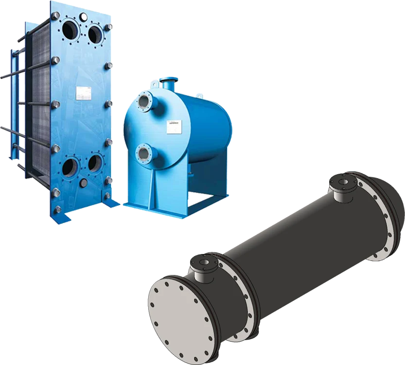
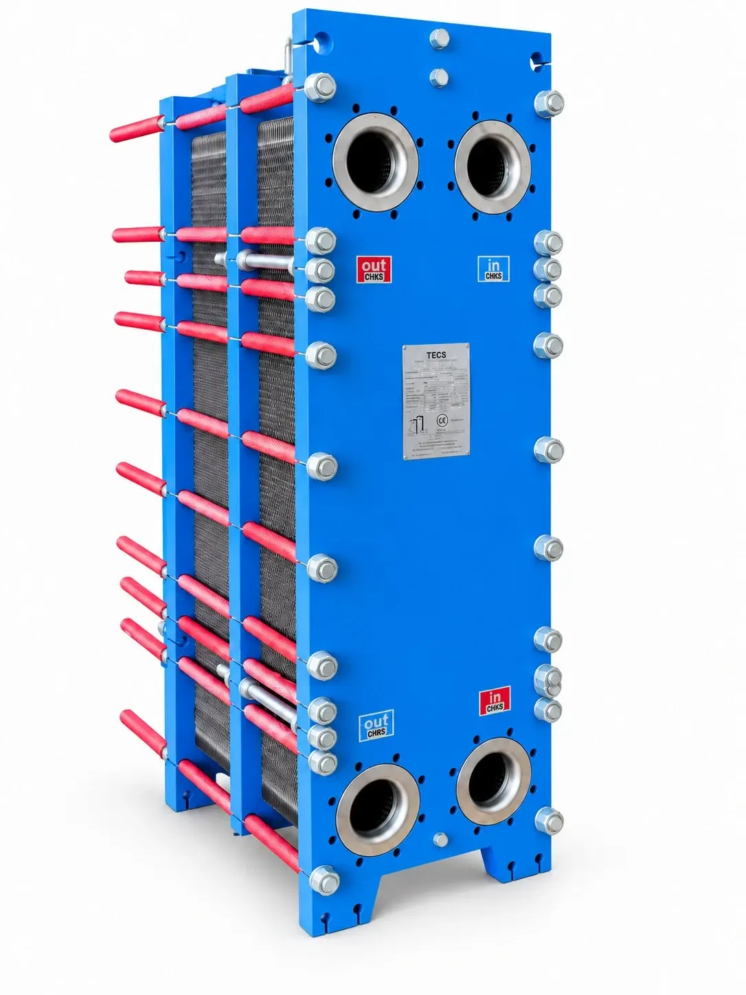
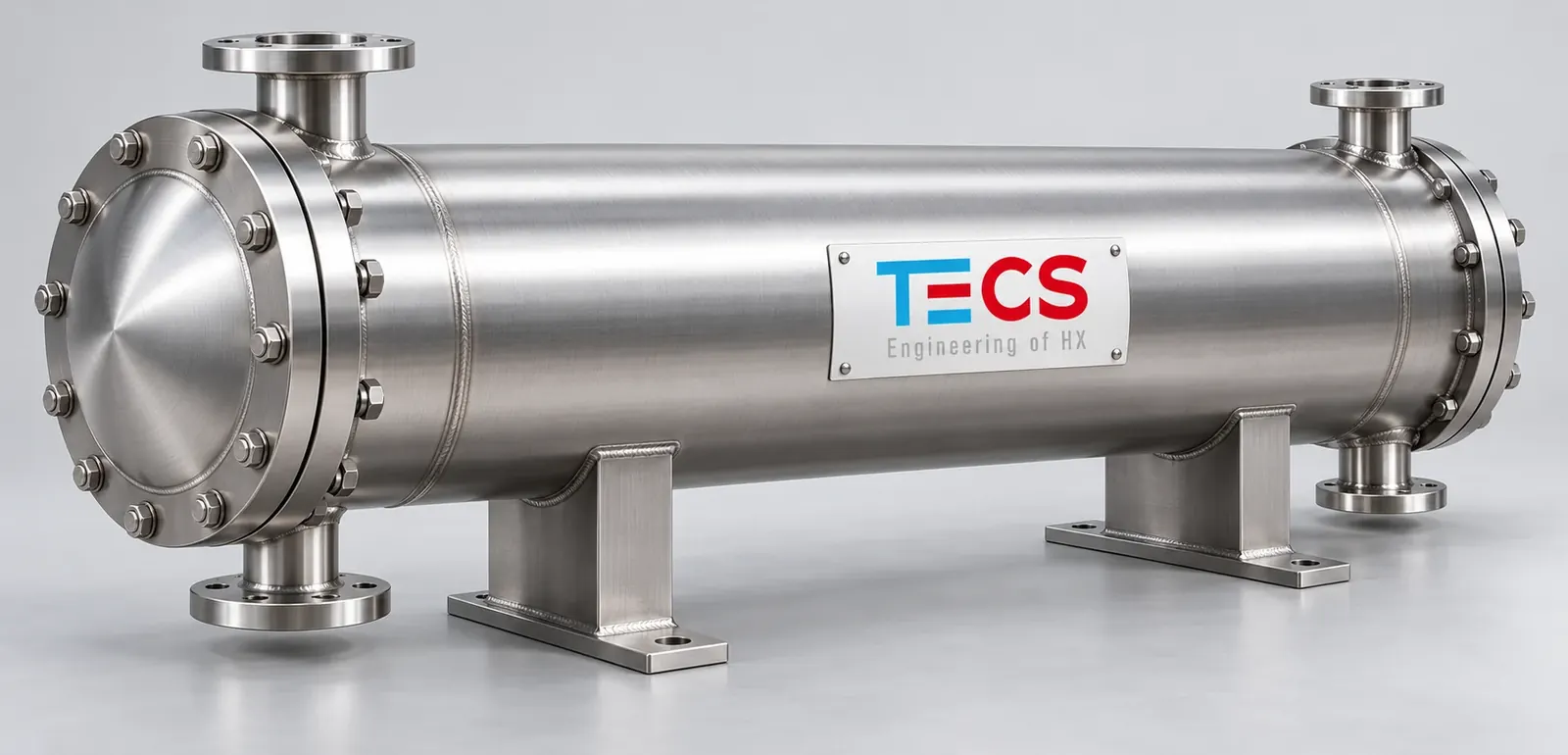
  • Plate heat exchangers, shell-and-tube heat exchangers, oil and fuel coolers selected for the circuit.
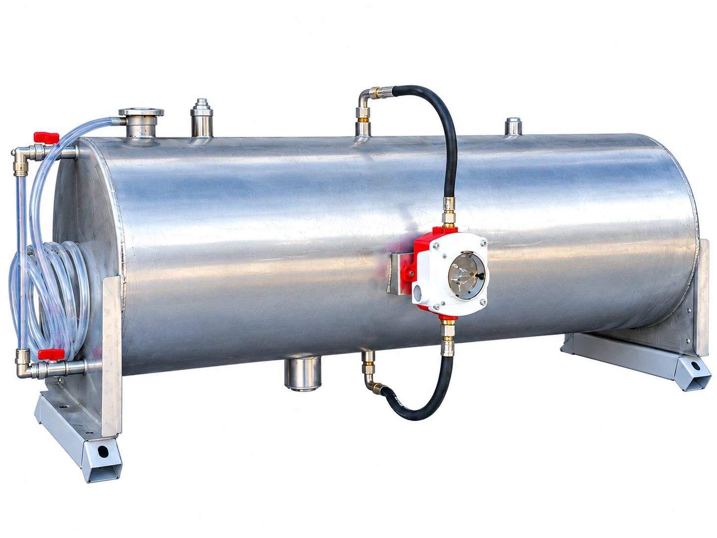
  • Expansion tanks in SS304L or SS316L, control panels and junction boxes.

ApplicationsPower GenerationCogeneration

Request a design

What It Is

Gas-engine power plants start and run their engines with pre-heated jacket water and recover heat from the LT and HT circuits. The heating module brings the pumps, control valves, heat exchangers, expansion tank and instrumentation of that circuit onto one skid, factory assembled and tested.

Scope

Pump sets with stand-by pumps, three-way control valves, plate or shell-and-tube heat exchangers, expansion tanks in SS304L or SS316L, level switches, thermometers, pressure gauges and the pipework between them. The control panel or junction box is wired on the skid. Skid frames and support structures for radiators and auxiliary equipment are built in the same workshop.

Integration

TECS designs the module around the engine manufacturer's circuit data and the plant layout, so the radiators and heating module arrive as one coordinated cooling system with matching connections.

Typical Scope Of Supply

  • Pumps, valves and heat exchangers on a common skid
  • Expansion tank, level switch, instrumentation
  • Pipework, insulation where specified
  • Control panel or junction box
  • Factory assembly and pressure test
  • P&ID, dimensional drawing, IOM manual

Technical Overview

Scope
Heating module, pump skid, support frame
Components
Pumps, valves, expansion tank, instrumentation
Heat exchangers
Plate or shell and tube
Tanks
SS304L / SS316L expansion tanks
Controls
Control panel, junction box, level switches
Testing
Factory assembled and pressure tested

Documentation

Every unit is delivered with its technical datasheet, dimensional drawing, fan curve and acoustic data, the test records of the factory pressure and function tests, and the installation, operation and maintenance manual. General arrangement drawings in PDF and DXF are issued for the project engineering, and the datasheet states the design point the unit was calculated for.

Contact Us

Send us the heat duty, the fluid temperatures and flow rates, the ambient conditions and the installation limits. We answer with a design proposal - or write to us on .

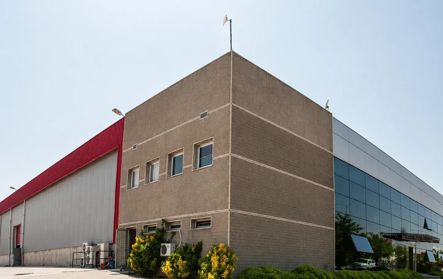
TECS Engineering factory, Menemen, İzmir