Two radiator offers for the same engine can differ by a third in size and price and both be correct - or one can be too small and look cheaper for it. The datasheet is where the difference shows, provided its lines are read together: a capacity means nothing without the conditions it belongs to, a sound level nothing without its distance. This guide walks through a TECS datasheet line by line and shows what to compare.
Capacity And Design Conditions
The first block gives, per circuit, the heat rejected in kW and the conditions it belongs to: the coolant inlet and outlet temperatures, the flow, the coolant type and glycol percentage, and the air inlet temperature - the design ambient - with the altitude and the humidity basis. Required and calculated capacity are shown as a pair; the calculated figure is a little above the required one, never below. Change any condition and the capacity changes with it: 500 kW at 45 °C ambient is a larger machine than 500 kW at 40 °C, and 500 kW on 50 % glycol larger again.
To compare two offers, put them on the same conditions first. An offer at 40 °C ambient against a specification at 45 °C is not cheaper; it is for another site.
Coolant Side And Air Side
The coolant block states the pressure drop across the radiator at the design flow, the connection sizes and whether the connections are at the same end or at opposite ends, and the circuit volume. The pressure drop is the figure to add to the pipework and to check against the engine maker's limit on external resistance - the datasheet gives the radiator alone.
The air block states the airflow in m³/h, the air outlet temperature and the face velocity, together with the coil data: fin material, fin pitch, number of rows, tube material and the coating, if any. A wide fin pitch and flat fins mean the designer expected dust; AlMg2.5 fins or an epoxy coating mean a corrosion class above C3. The face velocity tells how hard the fans work: high velocities give compact units and more noise.
Fans, Power And Sound
The fan block gives the fan type and diameter, the number of fans, EC or AC, the supply voltage and frequency, the installed motor power and the power consumption at the design point per fan and for the unit, and the fan speed. Installed power is what the switchgear must provide; consumption at the design point is what the plant pays for on the hottest day, and with speed control the yearly average is well below it.
The sound block gives the sound power level LwA of the unit and the sound pressure level LpA at stated distances - typically 1, 7 and 10 m - calculated over the unit's enveloping surface to EN 13487 and ISO 3744. A limit is always an LpA at a distance: compare the datasheet LpA at that distance, and for several units remember that the sum is louder than one. The TECS datasheet marks the line that applies to the limit in the enquiry.
Dimensions, Weights, Materials And Scope
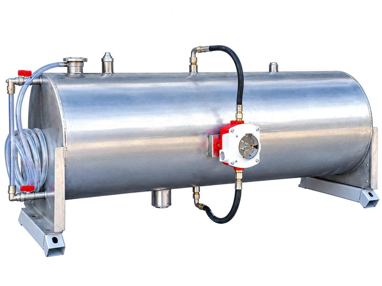
Length, width and height of the unit, the empty and the operating weight with coolant, the casing material and finish, the corrosion class, the expansion tank and its volume, the level switch, the junction box or control panel, the guards and the legs: the lines that the civil and electrical engineers need and that decide the transport. The scope of supply lists what is in the price and what is not - pipework, controls, commissioning.
TECS issues with every offer the datasheet, the dimensional drawing, the fan curve with the operating point and the acoustic data, and on request the general arrangement drawing in PDF and DXF. If an offer in your hands lacks a line discussed here, ask for it; if you want a second opinion on an existing datasheet, send it with the engine data sheet and the site conditions, and the comparison comes back as a proposal.
The Lines To Compare Between Two Offers
Capacity per circuit at the SAME ambient, altitude, coolant, glycol and temperatures
Coolant pressure drop against the engine maker's limit, after adding the pipework
Fin pitch, fin material and coating against the site's dust and corrosion class
Installed power and consumption at the design point
LpA at the distance of the limit, for one unit and for all units together
Scope of supply: tank, switch, panel, guards, legs, commissioning
Why are required and calculated capacity both printed?
So that the margin is visible. The unit is designed to deliver at least the required duty at the stated conditions; the calculated figure shows how much above it the delivered coil lands. A datasheet with one figure hides this.
Which ambient temperature should the datasheet show?
The one in the specification - the temperature at which the engine must still deliver its site rating. If offers differ in ambient, they are not comparable until they are brought to the same figure.
What is the difference between installed power and consumption?
Installed power is the sum of the motor ratings, the figure for the switchgear and cables. Consumption at the design point is what the fans draw on the design day; with speed control the average over the year is far lower.
Is the pressure drop on the datasheet the whole circuit?
No, only the radiator between its connections. Pipework, valves and other exchangers are added by the installer, and the sum is checked against the engine maker's limit.
Can TECS check a competitor's datasheet?
TECS can check any datasheet against the engine data sheet and the site conditions and show where it stands. Send both through the contact page or the file transfer page.
Send us the heat duty, the fluid temperatures and flow rates, the ambient conditions and the installation limits. We answer with a design proposal - or write to us on WhatsApp.